Building a Hexacopter
It’s been a while since I last wrote about multirotors and I have learned a lot since then. The DJI Phantom I started with had a few upgrades done to it:
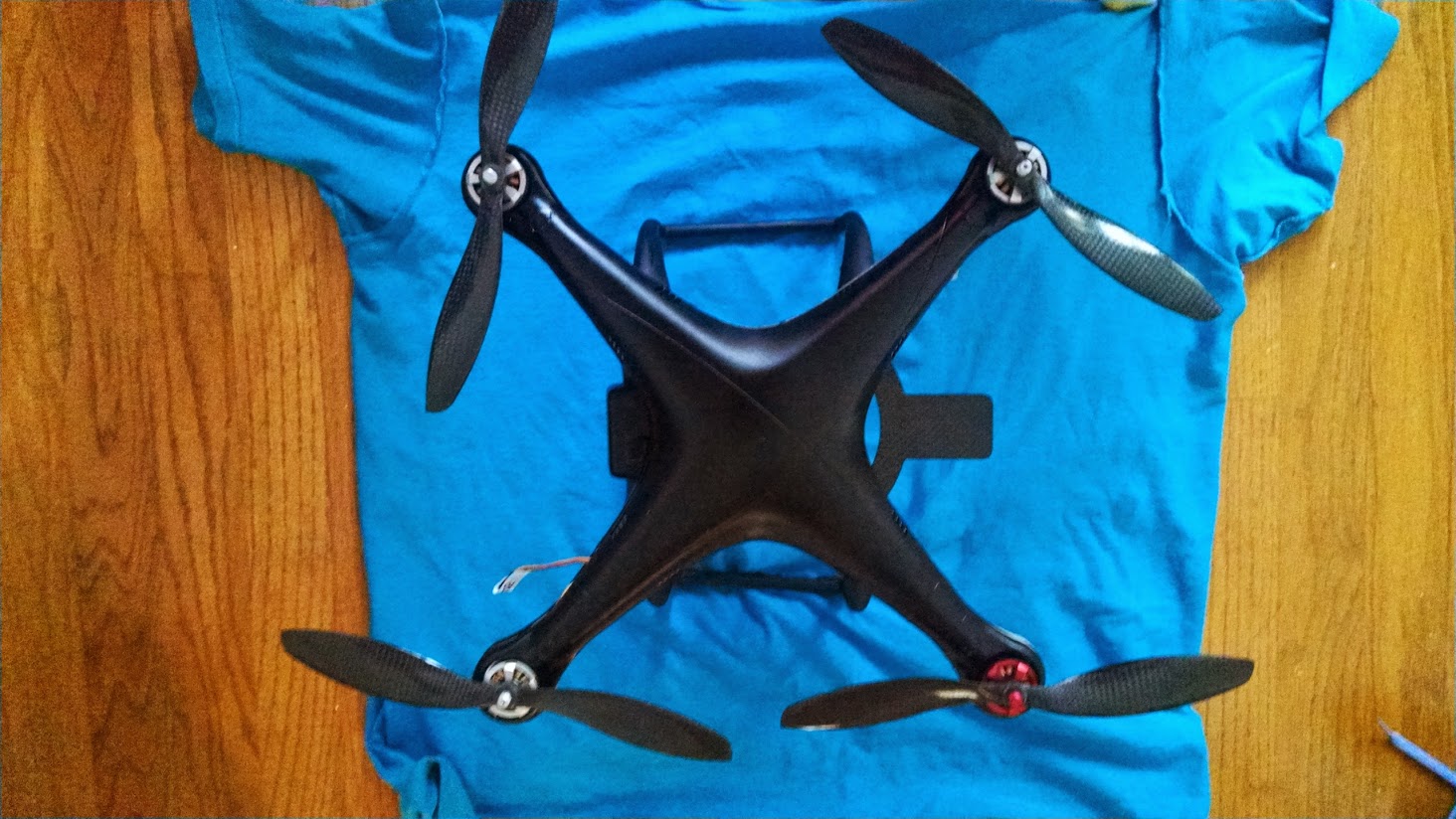
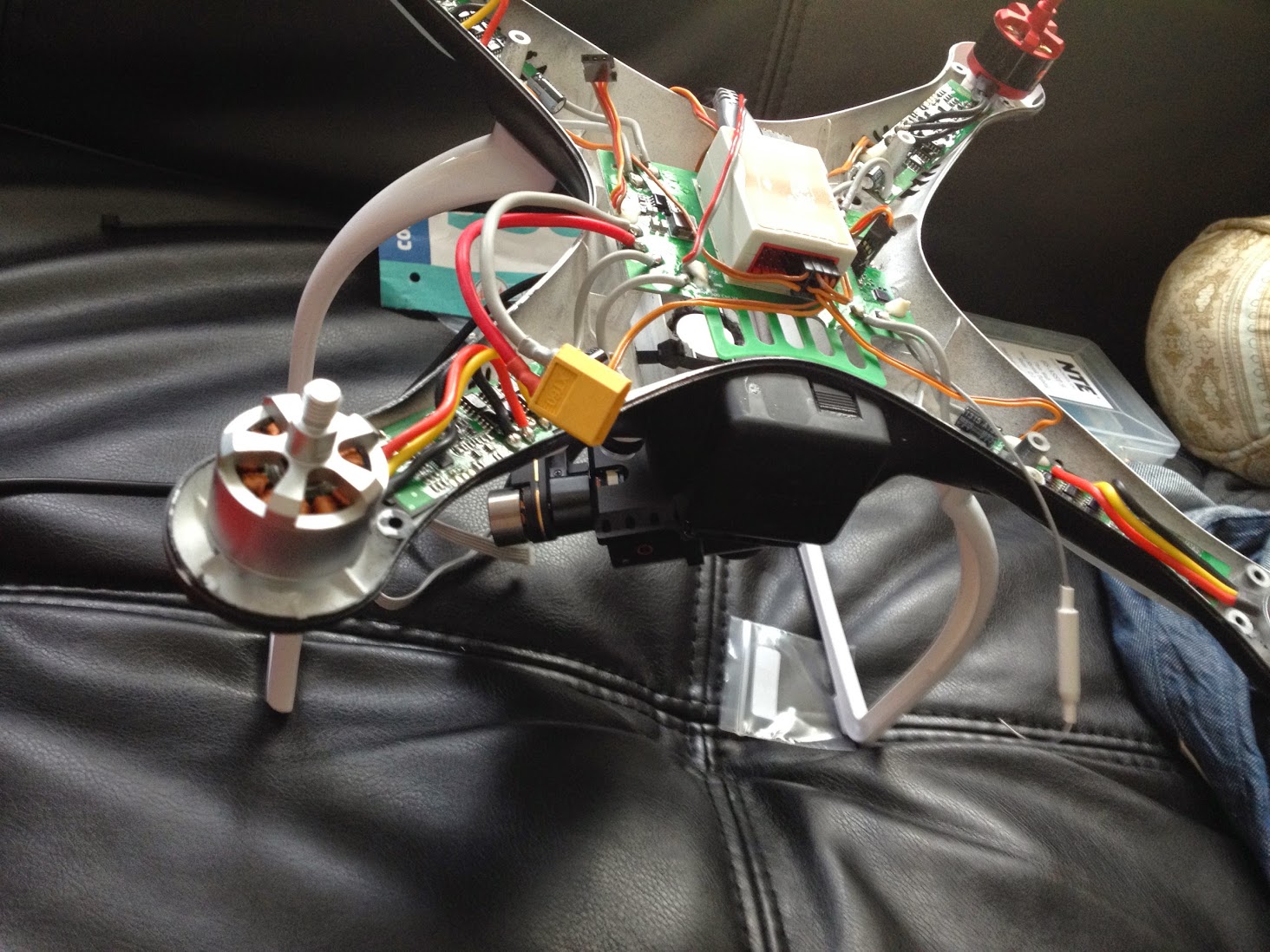
- Carbon fiber blades were added
- Body was painted black
- The mainboard was replaced with the H3-2D upgrade kit
- Smoother video and camera control were added with a H3-3D gimbal
- Taller landing gear was added
- The frame was modified to accommodate the gimbal
- FPV was added using a FatShark Attitude v2
- Added a video transmitter frame plane (carbon fiber as well)
The DJI that I had, the v1, had a number of glitches that periodically had to be fixed – most notably the receiver died twice on me. After the H3-2D upgrade, the receiver issue went away and the Phantom was capable of using the H3-3D, with gimbal control. It actually is not even supposed be able to do this, go Phantom!
FPV on the Phantom is super fun and I enjoyed it for many hours of flight. Being able to see what you are recording (via a GoPro in my case) is fun and also can result in better shots. To set up the GoPro for FPV, I wired the packaged transmitter to a break-out mini-USB cable that gives you video and ground. Once connected, the video just streams to the FatShark.
I had some CAN-BUS enhancements ready to go but needed to modify the connector to be able to support both the gimbal, on-screen-display (OSD), and bluetooth add-ons. Unfortunately, before the CAN-BUS could be added, I lost the drone.
The Hex!
I actually was sorta excited to lose the Phantom – it started to feel cramped! I couldn’t decide whether I wanted to build an inexpensive drone or go with the good stuff but I knew I wanted an open frame and potentially wanted a hexacopter. I ended up going cheap 🙂 I found an ARF kit hexacopter that had pre-chosen parts:
- F550 clone body
- 30A Electronic Speed Controllers (ESCs)
- 1000 kv motors
- KK multicopter computer
- ???? transmitter/receiver package
- battery and charger
The whole thing was sold at under $250 shipped which was about a third of what the brand name ones run so I gave it a chance. The box came with no instructions and just a jumble of parts:
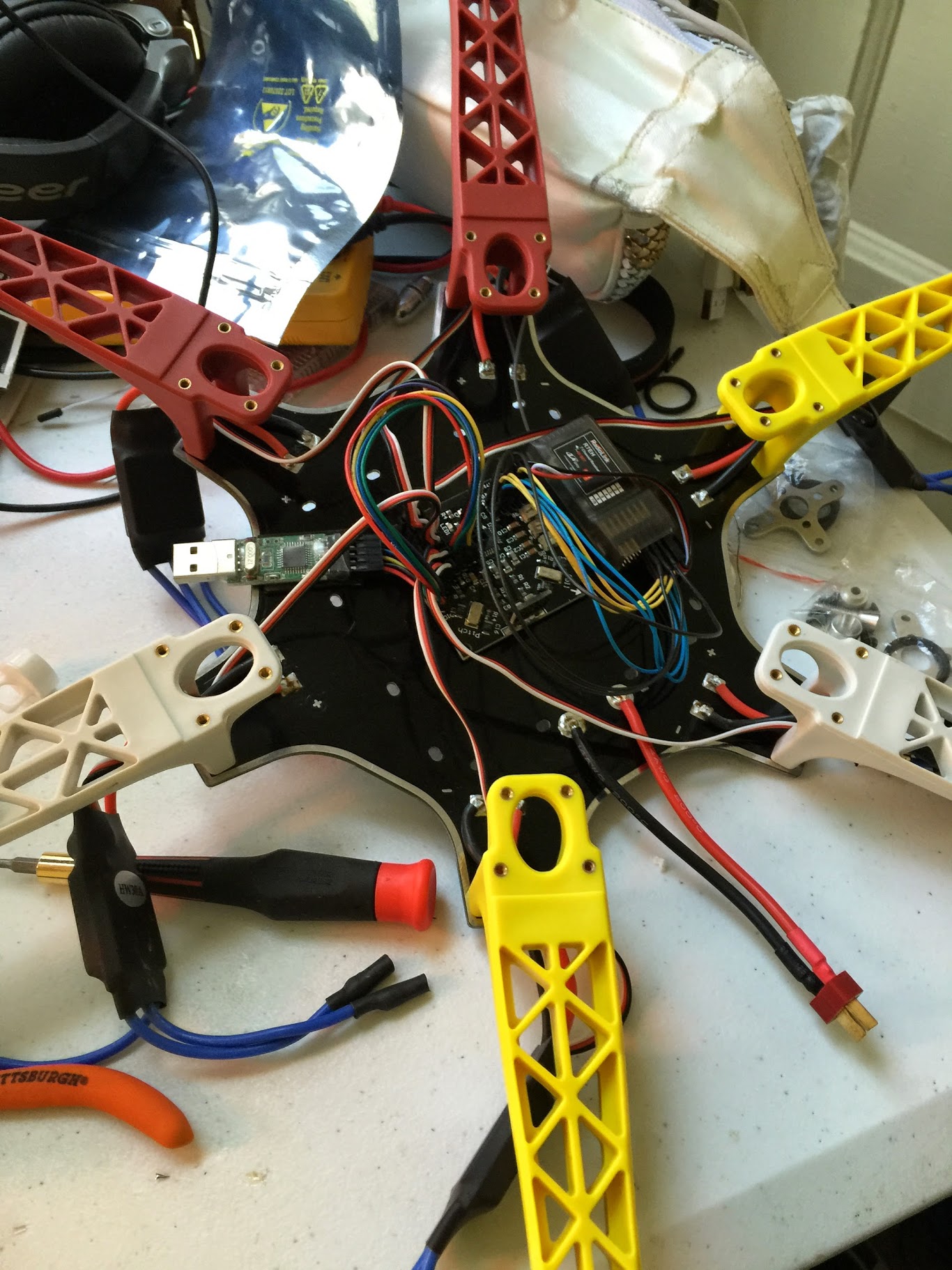
After eyeballing the pieces I decided to just hack it. My procedure was as follows:
- Solder parts to the mainboard
- Build out the frame
- Attach all the electronic parts
- Pair radio
- Calibrate and fly
Solder and attach parts to the mainboard
First, you solder the ESCs to the mainboard. Be extra careful that the + and – match, ground black negative -, red + positive. Next, solder power to the mainboard: double check the + and – match the ESCs – with ground black – and red +. You can see in the following picture to see a few soldered ESCs and the power cable around the edges of the mainboard:
Build out the arms
Attach motors to arms using Phillips head screws. This is relatively easy, just be careful to get the motors even with the arms where they attach. You might want to orient the arms in a way that works well for you, e.g. white in the front, yellow on the sides, and red in the back.
Slide ESC cables under the arms and attach using the mainboard screws. To determine which screws were the mainboard screws, I just chose whatever screws was the most numerous. Attach and tighten the screws once you have your cables tidy. Run motor wires under the arms so that they can tuck under and meet the ESC wires. Finally, you solder pin connectors to motors and ESCs and then heat-shrink wrap them. The following picture shows how I soldered the wires into the bullet pin connectors, it was a pain to do this but it worked.
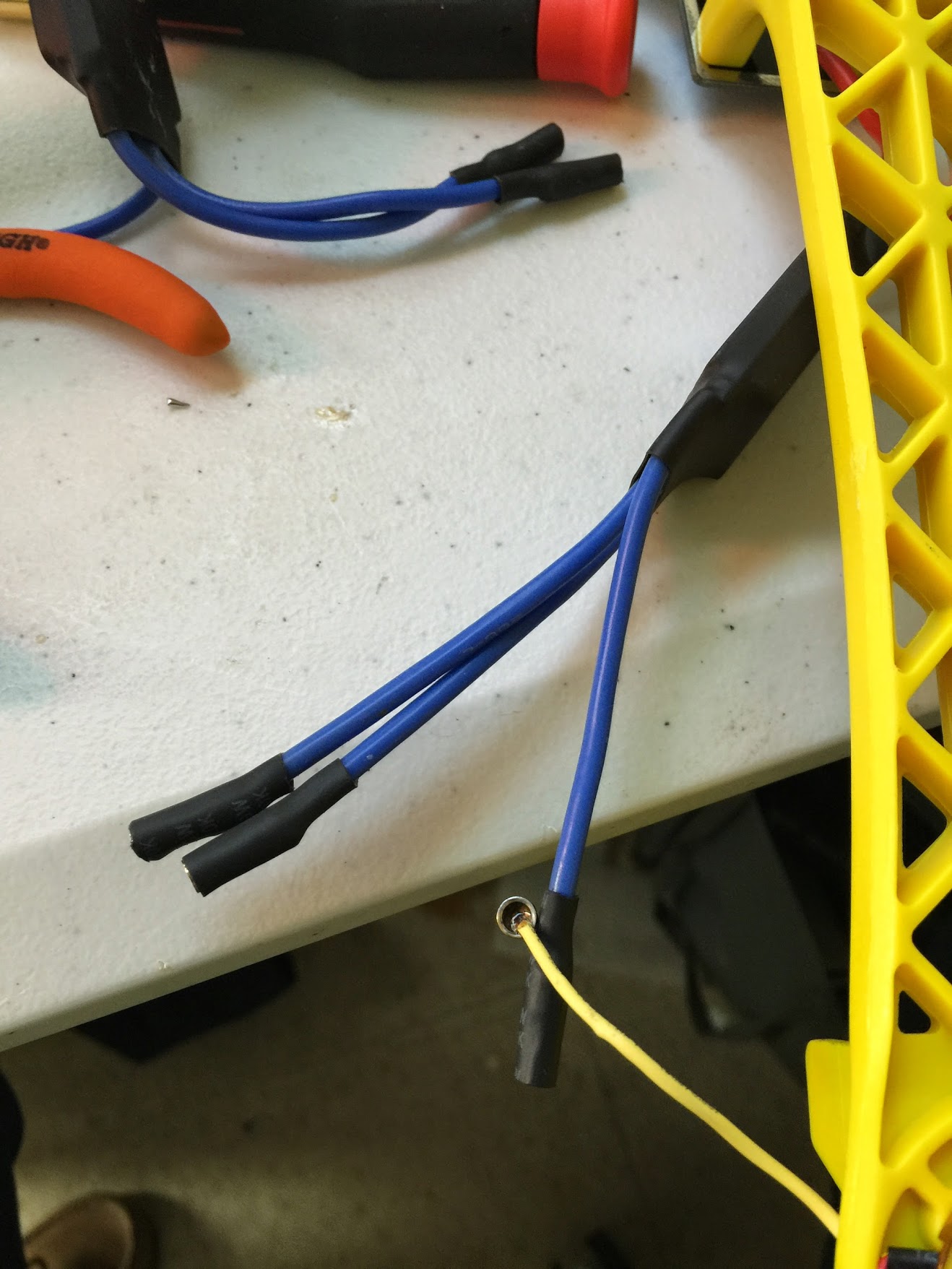
With the motors and ESCs wired, you can attach the motors to ESCs and can celebrate because there’s no more soldering!
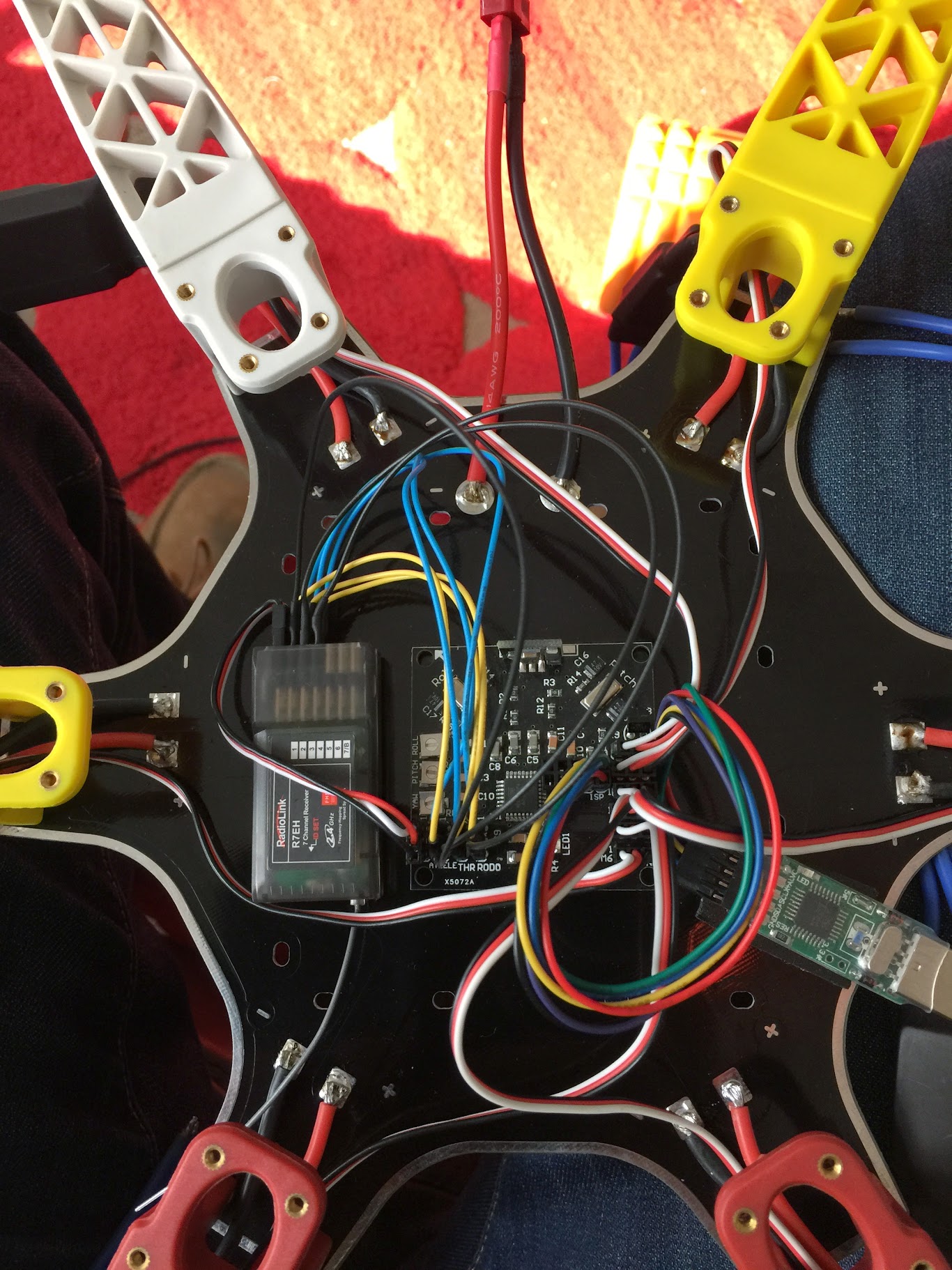
Connect the mainboard
Attach the pilot to the middle of the mainboard using double sided tape / velcro and orienting the arrow in the direction that you want to be forwards. Wire the pilot to the ESCs – pin 1 on the pilot goes to the arm at 1:30, pin 2 goes to the arm at 3:00, pin 3 to 5:00, and so on. Now attach the radio to the mainboard next to the pilot using double sided tape / velcro.
Now you will wire the radio to the pilot. You should use the KK blackboard pinout for pilot pins and the T6EHP-E manual for radio pinouts. When attaching the two, match the 1 pins on the first cables to orient the pins correctly, if done wrong, it will throw you off later when binding your radio.
Attach the USB programmer to the pilot. To orient it, I cheated because mine only went on one way with all the pins touching.
Program the pilot
Flash KK Firmware using the KK-flasher. On Windows, this requires a driver, USBasp, that is unsigned, requiring you to do bad things with Windows 8. Flash with the correct controller – mine was kk blackboard 168/PA (16kB flash). Choose a firmware for your configuration – I used X6 V2.9 XXControl KR by Minsoo Kim. When you flash the firmware, there are beeps, if it doesn’t work, make sure you selected the right controller in KK-flasher.
Connect the radio
This is the part where you bind the radio transmitter (TX) to receiver (RX). On my radio, I needed to hold a pin down on the receiver while the radio was in off throttle. After successfully binding, I could control the motors. It scared me the first time it worked. Note, if the receiver is not binding, check your wiring on the receiver you attached to the mainboard.
Calibrate
Next, you will need to make sure all the motors are working and are spinning in the right direction. You will start by slowly powering on your motors. To do this, you first must arm them using the firmware’s trigger that you may accidentally have activated while connecting the radio.
The firmware I used had a trigger done by moving the left stick to the bottom right. When the motors spin up, observe the rotation of the motors. I printed arrows to mark the observed direction of motor spin with left corresponding to a counterclockwise turn of the motor and right corresponding to a clockwise motor spin. This was done in case I got mixed up while flipping over the hexacopter. Why are you flipping over the hexacopter?
You do this because you must rewire the motors to ensure their rotation is corresponds to the directions indicated on this chart. Reversing the polarity of the motors (switching red and black) reverses to the motor’s direction. So, you just change the motors based on the observed directions until all the motors are spinning correctly. It’s relatively easy because of the pin connectors.
Final assembly
With the motors set right, attach the top mechanism using the same body screws as used before on the bottom and it will become much more stable. After that, fasten down the ESCs and motor cables so that they are snug against the frame. I used the included zip ties to accomplish this and it was relatively easy to find a spot to attach given the large frame.
Next you attach the propellers to the motors. The plastic bushings included with the propellers go into the propellers to match the screw size on the clamps (aka prop adapters, collet-type prop adapters in my kit) that attach to the motor pins. Speaking of, the motor pins were just the bolt, nut, and crimp pin and not the included gaskets and metal connectors. The crimping end of the bolt goes down onto the motors with the tightening cone on top and the propeller pushing down on the crimp bolt.
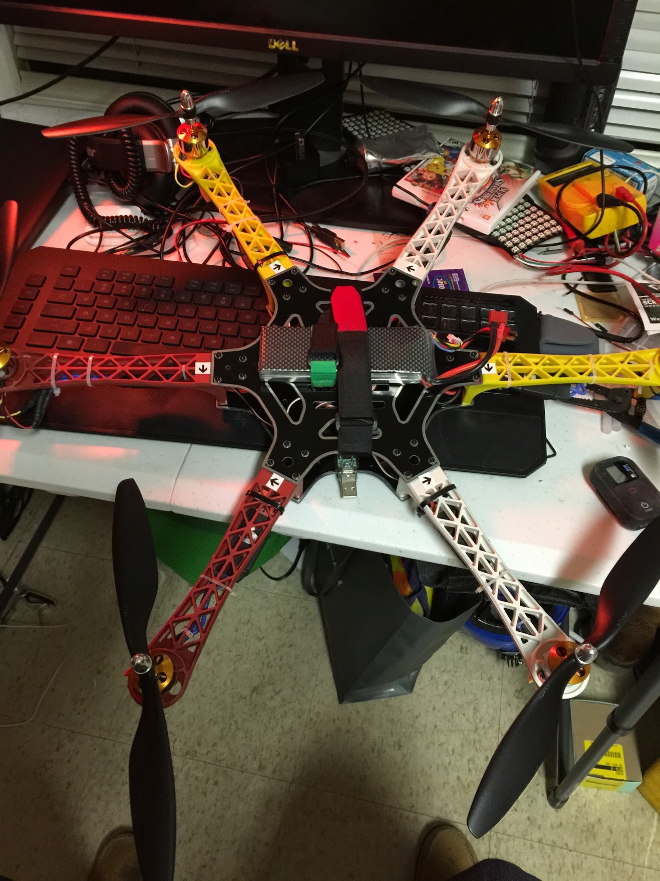
Note that multirotor blades spin with the rolling side facing the way the blade is turning. Match the blade direction to motor direction. If you look at the assembled picture below, you will notice the curving or scooping edge of the blade pointing in the direction of the arrows showing the motor direction.
Finally, attach the battery straps and strap in the battery and aha, you have a hexacopter.
Hover test
After putting everything together I took it into the alley and did a quick hover test. It hovered. I brought the craft back inside and then had a good look over it. The build quality was kinda questionable, but it actually flew and seemed relatively stable and controllable. All things considered, this was a bargain.
There were a few things though – the fit of the frame screws, having these weird pinch bolts that held on the blades, and the integrity of the blade/bushing setup all feels a little rickety. It was cheap though and for all I could tell resembled other similarly sized hexacopters. I can’t wait to actually fly it and see what happens!
Update:
Here is the Hexa flying in the park. I was just testing it so for safety I didn’t bring it high enough to actually fly around. Because I’m used to the Naza with Altitude and Position hold, this was a difficult flying experience. I’m going to try replacing the Flight Controller with a Naze32 equipped with GPS Antenna and will see if I fare better.

As you can see, lots of crashes and difficulty controlling the craft’s direction. I’m guessing there are a load of tweaks I still need to make on the FC before it is as stable and controllable as I want.
Ive been looking for something like this for four days now haha!!
I too have literally done the same thing, bought a clone f550 kit with the same escs, motors and tx&rx.
I initially built it and powered it up and the mottos were all in the wrong direction, I then stupidly changed the controller and firmware on the USB flasher and put some firmware on it- this completely messed it up, resulting in 3 days of me flashing loads of different firmwares on it with no success.
its just my luck that now I’m at work, I’ve seen this hahah. i will try this when i get home.
i noticed too that my receiver and kk board would only light up when i selected the 168p/PA 16kB flash.
at the moment I still can’t arm the hex. when i power it up the motors been in sequence and then stop, the tx has no control and won’t be armed by any of the different methods of gaming.
Ill try your way tonight !!
thanks for the help!!!
curtis